A VLAN, an acronym for virtual LAN (Virtual Local Area Network), is a method of creating logically independent networks even if they are located within the same physical network.
One of the advantages of using VLANs, when managing a local network, is the possibility of dividing it into several segments within the same local network, so that each segment corresponds to the same VLAN where we can group the machines by: Departments, projects, functions, users....
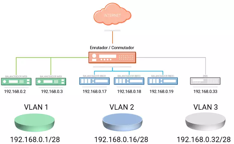
At a security level, VLANs are very useful, as they allow you to segment and restrict connectivity between different machines located in different logical segments of the same network, so that machines within the same VLAN can communicate with each other, but cannot communicate with machines in other VLANs of the same local network.
In SWHosting you can create a VLAN to communicate your different Cloud servers through the same local area network. In this way the transfer of network data between the servers of your VLAN can be done securely through this private network and without the need to use the public network connection of each server, intended exclusively to connect to the Internet.
To create a VLAN between your Cloud servers from the SWPanel you must follow the following steps:
1. Create the Networking container and add the servers to the Private VLAN. **2.
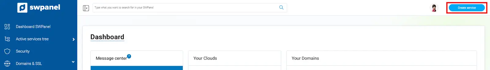
At the top right of your SWPanel click on the blue button "Create a Service ".
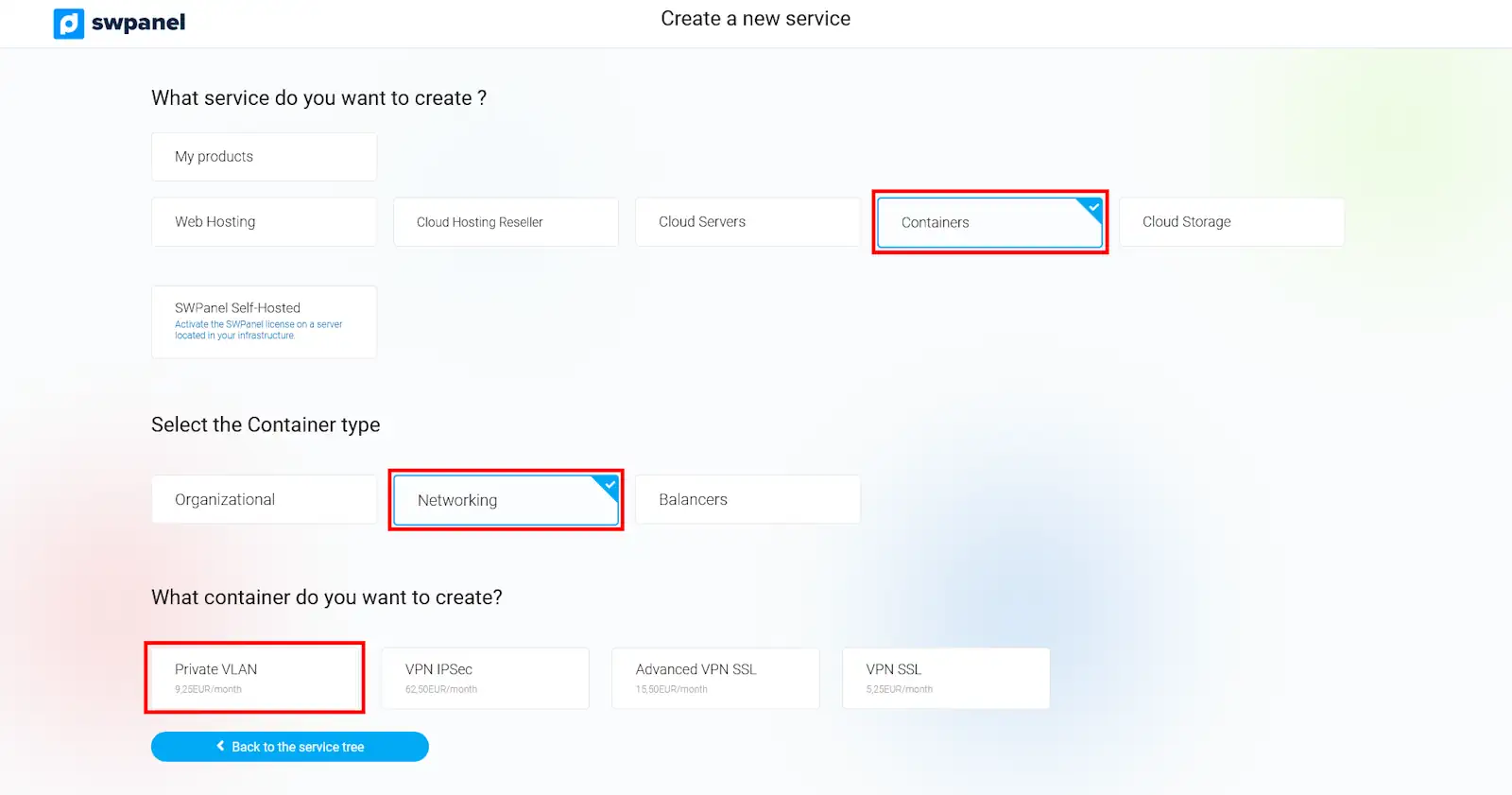
Among all the possible services you can create with your SWPanel choose "Containers ", "Networking " and finally "Private VLAN ".
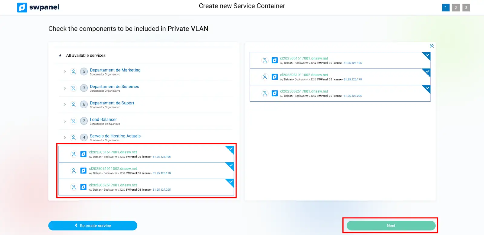
On the left side of the new window you will see a list of all your available servers, where you can select those Cloud servers you want to add to your VLAN. Once you have selected the servers included in the VLAN you will be able to check which ones you have chosen in the list of servers located on the right side of the window. To continue, click on the "Next" button.
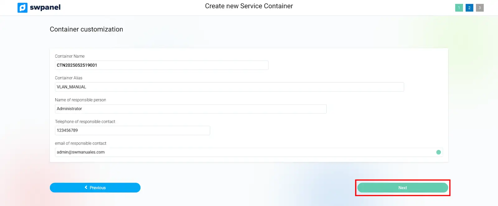
In the following window you will be able to define the nickname of the VLAN container by which it will be identified in your SWPanel. Also, you will be able to indicate the name of the person in charge, as well as his/her telephone number and email address. Once the data has been defined, click on the "Next " button.
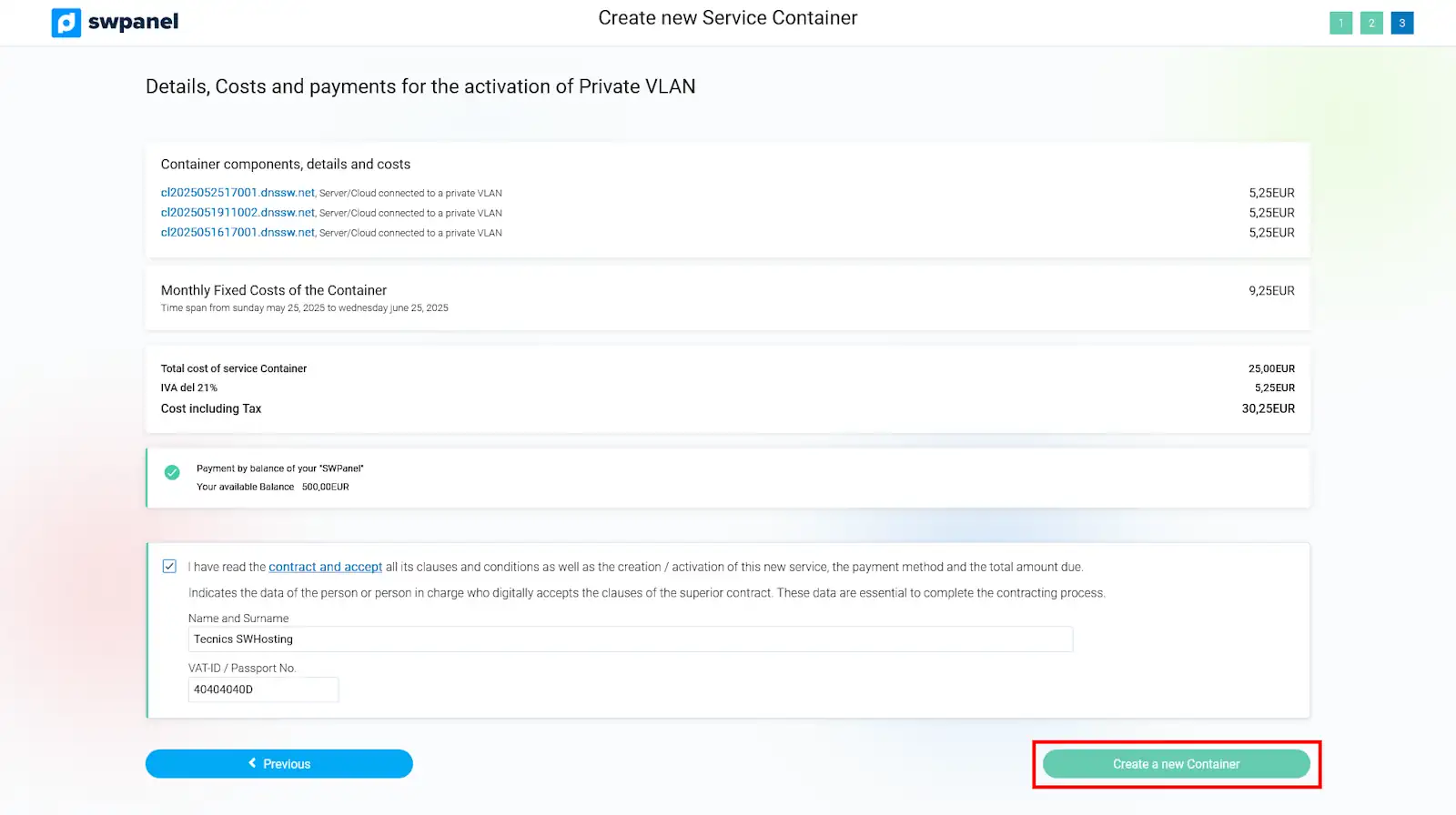
The following window will summarize the costs corresponding to the creation of the Private VLAN, according to the number of servers you have added to it. To accept the creation of the VLAN you must click on the "Create New Container " button.
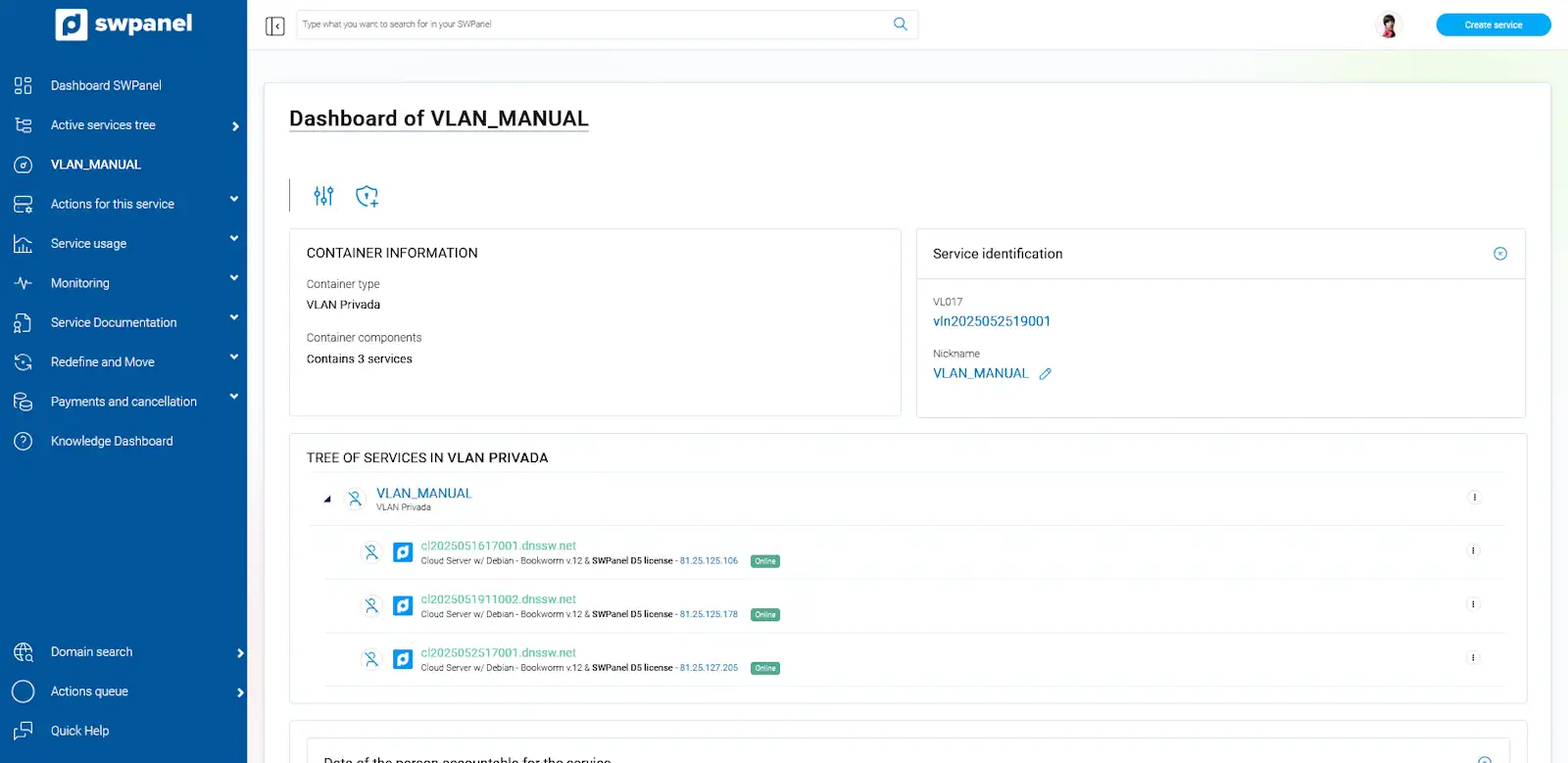
Once you have created your VLAN, you will be able to manage it, as well as the Cloud servers included in it, from the Dashboard in your SWPanel.
2. **Configure the Cloud servers to connect to the VLAN.
Once the VLAN has been created, you must individually configure each of the Cloud servers so that they can communicate through the connection to the private network.
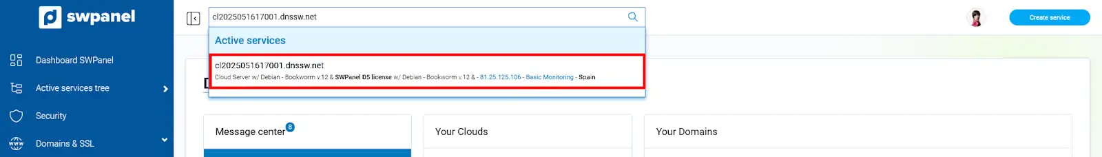
First, you will need to know the local network IP that was automatically assigned to each server when you created the VLAN container. From the search box of your SWPanel you will have to locate any of the Cloud servers that you have included in your VLAN to access their Dashboard.
Once you are in the server Dashboard, you must go to the left side menu and access the option "Actions on this service > Manage service IPs ".
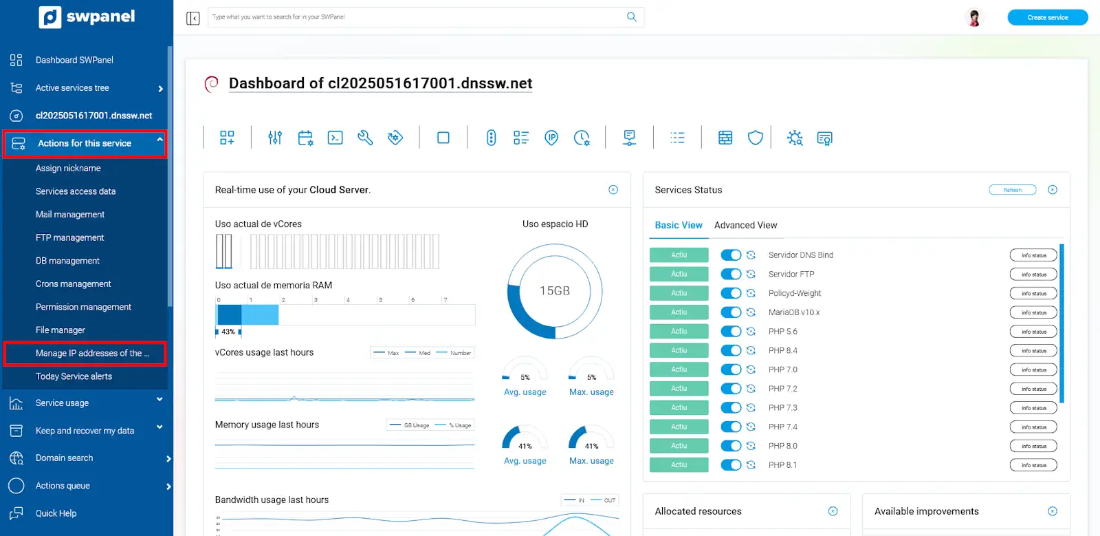
In the next window you will find the IP and the network mask that you must use to configure the local network interface of your Cloud server.
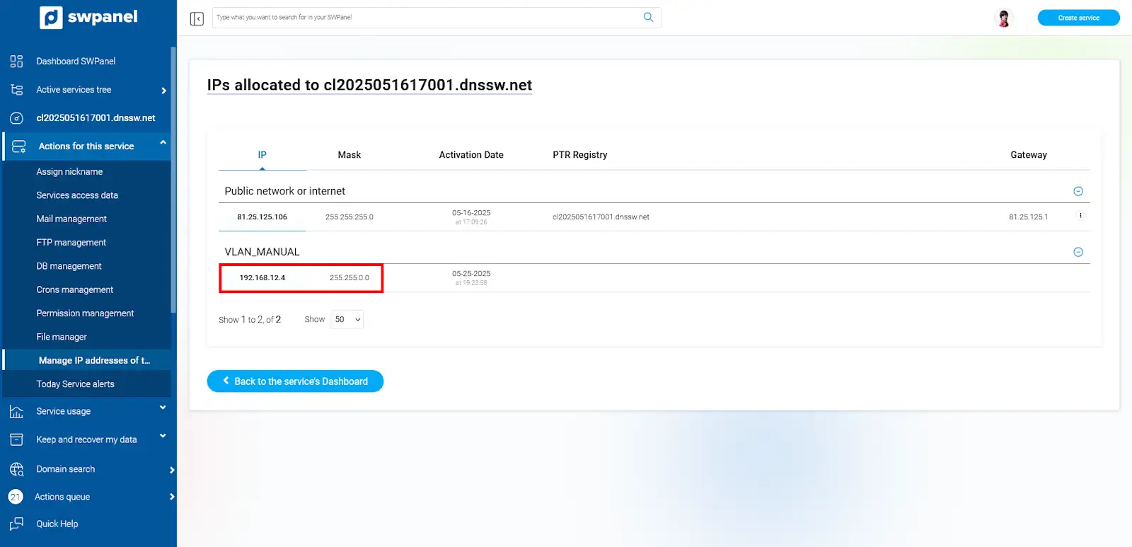
Make a note of both the IP and the mask, as you will need them later.
2.1 Configuring IP VLAN on a Debian / Ubuntu server Configuring IP VLAN on a Debian / Ubuntu server **Configuring IP VLAN on a Debian / Ubuntu server
In order for your Debian cloud server to access the virtual private network (VLAN) it must have a network interface connected to the VLAN and this interface must be configured so that it can "see" the other computers on the network.
To configure the network interface you must edit the "/etc/network/interfaces" file with your preferred editor (in this example the "vi" editor is used):
root@ce2019053111001:~# vi /etc/network/interfaces
And add the following configuration:
Note that if your cloud instance already had another configuration on "eth1", you should use "eth2" and so on consecutively.
It will look like this:
root@ce2019053111001:~# cat /etc/network/interfaces
auto lo
iface lo inet loopback
#
#
auto eth0
iface eth0 inet static
      address 185.61.124.136
      netmask 255.255.255.0
      gateway 185.61.124.1
      dns-nameservers  185.61.124.25 185.61.124.26
      dns-search  dnssw.net
auto eth1
iface eth1 inet static
	address 192.168.48.2
	netmask 255.255.0.0

root@ce2019053111001:~#
Once the configuration has been generated, all that remains is to apply it:
root@ce2019053111001:~# ifup eth1
Verify that the interface is configured and that you can "see" other computers in the VLAN:
root@ce2019053111001:~# ifconfig
eth0: flags=4163<UP,BROADCAST,RUNNING,MULTICAST>  mtu 1500
        inet 185.61.124.136  netmask 255.255.255.0  broadcast 185.61.124.255
        inet6 fe80::982d:edff:fec7:c5f1  prefixlen 64  scopeid 0x20<link>
        ether 9a:2d:ed:c7:c5:f1  txqueuelen 1000  (Ethernet)
        RX packets 6714581  bytes 333271211 (317.8 MiB)
        RX errors 0  dropped 0  overruns 0  frame 0
        TX packets 458188  bytes 66645406 (63.5 MiB)
        TX errors 0  dropped 0 overruns 0  carrier 0  collisions 0

eth1: flags=4163<UP,BROADCAST,RUNNING,MULTICAST>  mtu 1500
        inet 192.168.48.2  netmask 255.255.0.0  broadcast 192.168.255.255
        inet6 fe80::54f9:10ff:fed8:c74d  prefixlen 64  scopeid 0x20<link>
        ether 56:f9:10:d8:c7:4d  txqueuelen 1000  (Ethernet)
        RX packets 0  bytes 0 (0.0 B)
        RX errors 0  dropped 0  overruns 0  frame 0
        TX packets 7  bytes 550 (550.0 B)
        TX errors 0  dropped 0 overruns 0  carrier 0  collisions 0

lo: flags=73<UP,LOOPBACK,RUNNING>  mtu 65536
        inet 127.0.0.1  netmask 255.0.0.0
        inet6 ::1  prefixlen 128  scopeid 0x10<host>
        loop  txqueuelen 1  (Local Loopback)
        RX packets 0  bytes 0 (0.0 B)
        RX errors 0  dropped 0  overruns 0  frame 0
        TX packets 0  bytes 0 (0.0 B)
        TX errors 0  dropped 0 overruns 0  carrier 0  collisions 0

root@ce2019053111001:~#
Finally verify that you can see other computers on the same network (you must know their IP, in this example visibility is verified with the IP "192.168.48.3"):
root@ce2019053111001:~# ping 192.168.48.3 -c 4
PING 192.168.48.3 (192.168.48.3) 56(84) bytes of data.
64 bytes from 192.168.48.3: icmp_seq=1 ttl=64 time=0.392 ms
64 bytes from 192.168.48.3: icmp_seq=2 ttl=64 time=0.392 ms
64 bytes from 192.168.48.3: icmp_seq=3 ttl=64 time=0.417 ms
64 bytes from 192.168.48.3: icmp_seq=4 ttl=64 time=0.428 ms

--- 192.168.48.3 ping statistics ---
4 packets transmitted, 4 received, 0% packet loss, time 3073ms
rtt min/avg/max/mdev = 0.392/0.407/0.428/0.021 ms
root@ce2019053111001:~#
With this test you can see that the cloud instance is correctly configured at the VLAN level.
2.2 Configure IP VLAN on a CentOS / RedHat / Oracle Linux server.
In order for your CentOS cloud server to access the virtual private network (VLAN), it must have a network interface connected to the VLAN and this interface must have a configuration so that it can "see" the other computers on that network.
To configure the network interface you must create a file with the configuration you want to apply. You must position yourself in the folder where the network configurations are located:
[root@ce2019060512001 ~]# cd /etc/sysconfig/network-scripts/
In this folder you will find the configurations for each device divided into different files. Note the files named "ifcfg-eth".
[root@ce2019060512001 network-scripts]# ls
ifcfg-eth0   ifdown-eth   ifdown-post    ifdown-Team      ifup-aliases  ifup-ipv6   ifup-post    ifup-Team      init.ipv6-global
ifcfg-lo     ifdown-ippp  ifdown-ppp     ifdown-TeamPort  ifup-bnep     ifup-isdn   ifup-ppp     ifup-TeamPort  network-functions
ifdown       ifdown-ipv6  ifdown-routes  ifdown-tunnel    ifup-eth      ifup-plip   ifup-routes  ifup-tunnel    network-functions-ipv6
ifdown-bnep  ifdown-isdn  ifdown-sit     ifup             ifup-ippp     ifup-plusb  ifup-sit     ifup-wireless
[root@ce2019060512001 network-scripts]#
You must create a file with the configuration of the new device:
Note that if your cloud instance already had another configuration on "eth1", you should use "eth2" and so on.
Edit the file directly and add the following configuration:
[root@ce2019060512001 network-scripts]# vi ifcfg-eth1
DEVICE="eth1"
ONBOOT=yes
TYPE=Ethernet
BOOTPROTO=static
IPADDR=192.168.48.3
NETMASK=255.255.0.0
IPV6INIT=no
[root@ce2019060512001 network-scripts]#
Once the configuration has been generated, all that remains is to apply it:
[root@ce2019060512001 network-scripts]# ifup eth1
Verify that the interface is configured and that you can "see" other computers in the VLAN:
[root@ce2019060512001 network-scripts]# ifconfig
eth0: flags=4163<UP,BROADCAST,RUNNING,MULTICAST>  mtu 1500
        inet 185.61.124.40  netmask 255.255.255.0  broadcast 185.61.124.255
        inet6 fe80::dc3a:14ff:fe7e:1ea7  prefixlen 64  scopeid 0x20<link>
        ether de:3a:14:7e:1e:a7  txqueuelen 1000  (Ethernet)
        RX packets 2284394  bytes 114577899 (109.2 MiB)
        RX errors 0  dropped 0  overruns 0  frame 0
        TX packets 121481  bytes 17467015 (16.6 MiB)
        TX errors 0  dropped 0 overruns 0  carrier 0  collisions 0

eth1: flags=4163<UP,BROADCAST,RUNNING,MULTICAST>  mtu 1500
        inet 192.168.48.3  netmask 255.255.0.0  broadcast 192.168.255.255
        inet6 fe80::2811:44ff:fecd:7118  prefixlen 64  scopeid 0x20<link>
        ether 2a:11:44:cd:71:18  txqueuelen 1000  (Ethernet)
        RX packets 14  bytes 694 (694.0 B)
        RX errors 0  dropped 0  overruns 0  frame 0
        TX packets 13  bytes 838 (838.0 B)
        TX errors 0  dropped 0 overruns 0  carrier 0  collisions 0

lo: flags=73<UP,LOOPBACK,RUNNING>  mtu 65536
        inet 127.0.0.1  netmask 255.0.0.0
        inet6 ::1  prefixlen 128  scopeid 0x10<host>
        loop  txqueuelen 1000  (Local Loopback)
        RX packets 0  bytes 0 (0.0 B)
        RX errors 0  dropped 0  overruns 0  frame 0
        TX packets 0  bytes 0 (0.0 B)
        TX errors 0  dropped 0 overruns 0  carrier 0  collisions 0

[root@ce2019060512001 network-scripts]#
Finally verify that you can see other computers on the same network (you must know their IP, in this example the visibility is verified with the IP "192.168.48.2"):
[root@ce2019060512001 network-scripts]# ping 192.168.48.2 -c 4
PING 192.168.48.2 (192.168.48.2) 56(84) bytes of data.
64 bytes from 192.168.48.2: icmp_seq=1 ttl=64 time=1.25 ms
64 bytes from 192.168.48.2: icmp_seq=2 ttl=64 time=0.365 ms
64 bytes from 192.168.48.2: icmp_seq=3 ttl=64 time=0.404 ms
64 bytes from 192.168.48.2: icmp_seq=4 ttl=64 time=0.377 ms

--- 192.168.48.2 ping statistics ---
4 packets transmitted, 4 received, 0% packet loss, time 3001ms
rtt min/avg/max/mdev = 0.365/0.600/1.255/0.378 ms
[root@ce2019060512001 network-scripts]#
With this test you can see that the cloud instance is correctly configured at the VLAN level.
2.3 Configuring IP VLANs on a Windows server.
In order for your cloud server with Windows operating system to access the virtual private network (VLAN), it must have a network interface connected to the VLAN and this interface must have a configuration so that it can "see" the other computers on that network.
To do this, you must first access the Windows "Control Panel" (if you do not know how to open it, use the cortana search engine or click on the Start button and type "control panel", it will appear in the results).
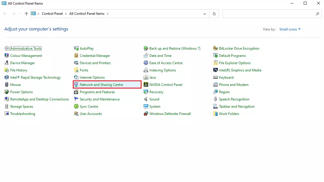
Once you are inside the control panel, open the "Network and Sharing Center". In the side menu, click on "Change adapter settings".
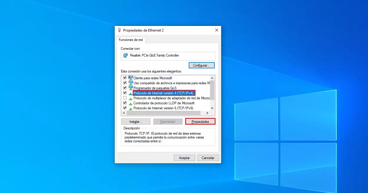
Identify the VLAN network interface, it will appear with a name "Ethernet 2". To proceed to configure it use the "Properties" menu by right-clicking or double-clicking on the interface icon and then "Properties".
Note that if your cloud instance already had another configuration in "Ethernet 2", you will have to use "Ethernet 3" and so on.
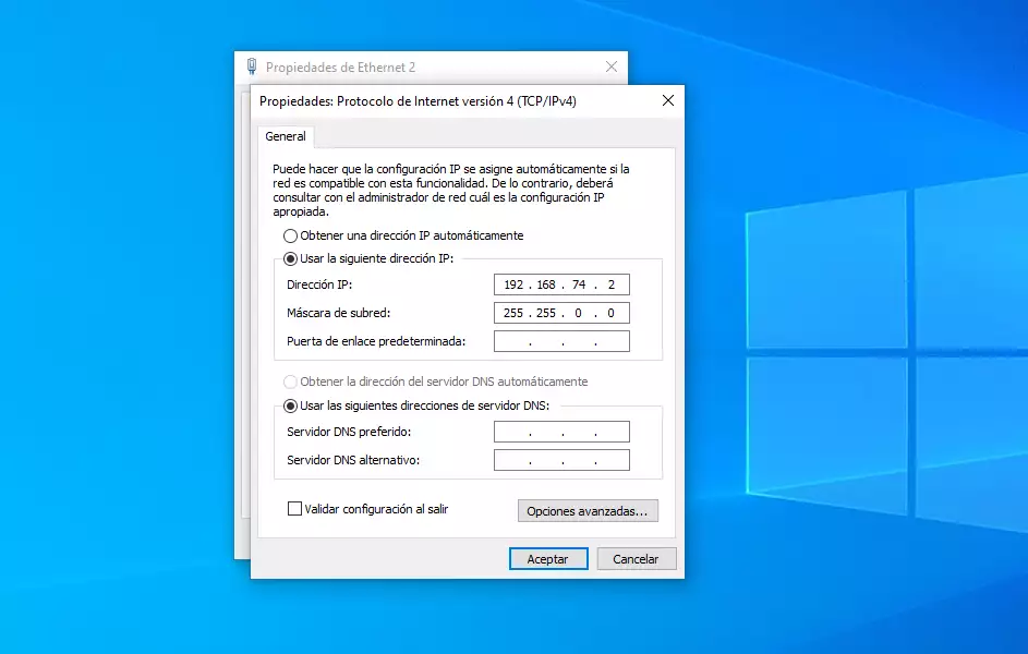
Proceed to select the "Internet Protocol version 4 (TCP/IPv4) and then "Properties".
Enter the configuration with the data obtained previously:
Click "OK" and close the previous windows.
Verify that the interface is configured and that you can "see" other computers in the VLAN, using the Windows "CMD" ("Start", type "cmd" and "Enter"):
C:\Users\Administrador.CE2019060510002>ipconfig

Windows IP configuration


Ethernet Internet Adapter:

   Specific DNS suffix for the connection. . : dnssw.net
   Link: local IPv6 address. . . : fe80::3402:2f51:7955:1fbb%5
   IPv4 address. . . . . . . . . . . . . . : 185.61.124.131
   Subnet mask . . . . . . . . . . . . : 255.255.255.0
   Default Gateway . . . . . : 185.61.124.1

Ethernet VLAN adapter:

   Specific DNS suffix for the connection. . :
   Link: local IPv6 address. . . : fe80::1cfe:7dc1:2abe:70e2%13
   IPv4 address. . . . . . . . . . . . . . : 192.168.48.4
   Subnet mask . . . . . . . . . . . . : 255.255.0.0
   Default Gateway . . . . . :

Tunnel adapter isatap.dnssw.net:

   State of the media. . . . . . . . . . . : disconnected media
   Specific DNS suffix for the connection. . : dnssw.net

Isatap tunnel adapter. {A770B8C8-53FC-454F-8620-D8567917E18F}:

   State of the media. . . . . . . . . . . : disconnected media
   Specific DNS suffix for the connection. . :

C:\Users\Administrador.CE2019060510002>
Finally, verify that you can see other computers on the same network (you must know their IP, in this example visibility is verified with the IP "192.168.48.2"):
C:\Users\Administrador.CE2019060510002>ping 192.168.48.2

Pinging 192.168.48.2 with 32 bytes of data:
Answer from 192.168.48.2: bytes=32 time=2ms TTL=64
Answer from 192.168.48.2: bytes=32 time<1m TTL=64
Answer from 192.168.48.2: bytes=32 time<1m TTL=64
Answer from 192.168.48.2: bytes=32 time<1m TTL=64

Ping statistics for 192.168.48.2:
    Packets: sent = 4, received = 4, lost = 0.
    (0% lost),
Approximate round-trip times in milliseconds:
    Minimum = 0ms, Maximum = 2ms, Average = 0ms.

C:\Users\Administrador.CE2019060510002>
With this test you can see that the cloud instance is correctly configured at the VLAN level.